|
|
|
| |
|
| |
|
|
|
|
| |
|
|
|
|
|
|
|
| |
|
|
|
|
| |
|
|
|
|
| |
1.Application |
| |
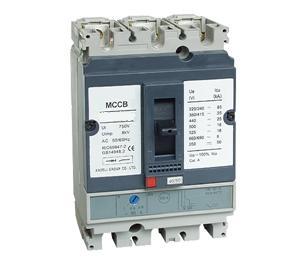
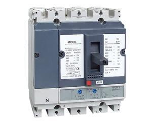
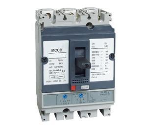
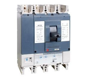
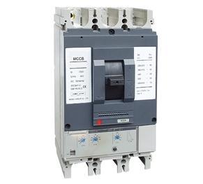
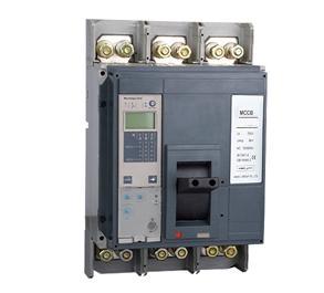
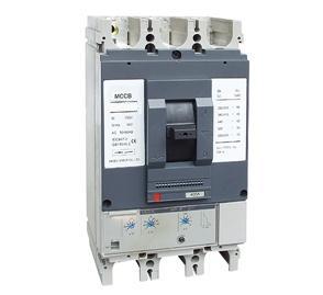
SM2 series moulded case circuit breaker is one of breaker which adopts international ad-vanced design, manufacture technology to develop. The rated insulating voltage is 750V, suit-able for AC 50Hz(60Hz),rated working voltage 690V or below, rated working current is 12.5A to1250A of circuit and used in distributing electric energy, and non-frequent breaking in the nor-mal conditions , protecting the current& equipment from overload&under voltage, circuit breakerwith rated frame current 400A or below,can be used in mousecage motor's non-frequent start,breaking during working, protecting motor from overload, short circuit&undervoltage,the prod-uct conforms to IEC60947-2 standard. |
| |
| |
2.Main Technical Specifications |
| |
| Type |
Pole number |
Rated insulating voltage(V) |
Rated operating voltage(V) |
Rated ultimate short circuit breaking capacity Icu (KA) at 380/415V |
Rated servies short circuit breaking capacity Ics at 380/415V(KA) |
Operation performance |
Utilization category |
| ON |
OFF |
SM2-100N |
3, 4pole |
750 |
690 and below |
25 |
25 |
1500 |
8500 |
A |
SM2-100H |
70 |
70 |
SM2-100L |
150 |
150 |
SM2-160N |
36 |
36 |
1000 |
7000 |
SM2-160H |
70 |
70 |
SM2-160L |
150 |
150 |
SM2-250N |
36 |
36 |
1000 |
7000 |
SM2-250H |
70 |
70 |
SM2-250L |
150 |
150 |
SM2-400N |
45 |
45 |
1000 |
4000 |
SM2-400H |
70 |
70 |
SM2-400L |
150 |
150 |
SM2-630N |
45 |
45 |
1000 |
4000 |
SM2-630H |
70 |
70 |
SM2-630L |
150 |
150 |
SM2-1250N |
3 pole |
50 |
37.5 |
1000 |
4000 |
SM2-1600N |
50 |
37.5 |
|
Note:1. The N-pole breaker has no protection which closing and opening with the other three poles. 2. The type of thermal magnetic for SM2-400/630 has no four poles. |
| |
| |
|
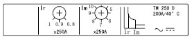
3 Trip units main technical parameter |
|
Thermal magnetic release |
|
|
| Type |
Rated currentIn(A) |
Note |
SM2-100 |
12.5,16,20,25,32,40,50,63,80,100 |
Tadjustable (0.8~1In)M adjustable (5~10In) |
SM2-160 |
16,20,25,32,40,50,63,80,100,125,160 |
SM2-250 |
160,180,200,225,250 |
SM2-400 |
315,350,400 |
SM2-630 |
400,500,630 |
SM2-1250 |
800,1000,1250 |
Tadjustable (0.8~1In)M fixed |
SM2-1600 |
1000,1250,1600 |
|
| |
Electronic release |
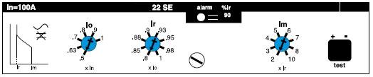
SM2 22SE: protection of low-voltage distribution networks for SM2-100\160\250 |
|
1. Overload protection with adjustable threshold |
2. Short-circuit protection with adjustable threshold |
3. Load indication : light at 90% of Ir setting threshold; |
Flashing at 105% or more of Ir setting threshold |
| |
| Type |
Rated current In(A) |
Note |
SM2-100 |
40,100 |
Ir=0.4~1×In(adjustable 48 setting)
Tripping between 1.05~.3×Ir (IEC60947-2)
(Long-time overload protection)
Im=2-3-4-5-6-7-8-10×Ir
(Short-circuit protection) |
SM2-160 |
40,100,160 |
SM2-250 |
40,100,160,250 |
|
| |
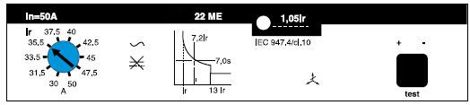
SM2 22ME: protection of motor for SM2-100\160\250
|
| |
|
1. Overload protection with adjustable threshold, as defined by IEC60947-4 (2) tripping class 10 |
2. Short-circuit protection with fixed threshold (13xIr) |
3. phase failure protection (tripping time delay between 3.5s-6s) |
4. Load indication : dark less than 105% of Ir setting threshold; |
Flashing at 105% or more of Ir setting threshold |
|
| Type |
Rated current In(A) |
Note |
SM2-100 |
40,50,80,100 |
Ir=0.6-0.63-0.67-0.71-0.75-0.80-0.85-0.90-0.95-1×In |
SM2-160 |
40,50,80,100,150 |
SM2-250 |
40,50,80,100,150,220 |
|
| |
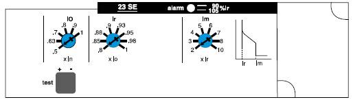
SM2 23SE: protection of low-voltage distribution networks for SM2-400\630 |
|
|
1. Overload protection with adjustable threshold
|
2. Short-circuit protection with adjustable threshold
|
3. Load indication : light at 90% of Ir setting threshold; |
Flashing at 105% or more of Ir setting threshold
|
|
| Type |
Rated current In(A) |
Note |
SM2-400 |
400 |
Ir=0.4~1×In(adjustable 48 setting)
Tripping between 1.05~1.3×Ir (IEC60947-2)
(Long-time overload protection)
Im=2-3-4-5-6-7-8-10×Ir
(Short-circuit protection) |
SM2-630 |
630 |
|
| |
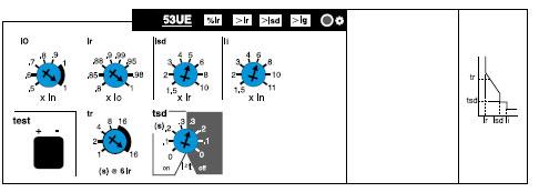
SM2 53UE: protection of low-voltage distribution networks for SM2-400\630 |
| |
|
1. Overload protection with adjustable threshold, as defined by IEC60947-2 |
2. Short-circuit protection with adjustable threshold |
3. Instantaneous short-circuit protection |
4. Earth fault protection with adjustable threshold |
5. Load indication : light at 90% of Ir setting threshold; |
Flashing more than Ir setting threshold |
6. Fault indication
|
LEDs indicates the type of fault that caused tripping |
Overload (LT protection) or abnormal component temperature (>Ir); |
Short-circuit (ST or instantaneous protection)( >Im); |
Earth fault (if earth fault protection option is present)(Ig); |
Microprocessor malfunction (both (>Ir) and ( >Im) LEDs go on ,plus the (Ig) LEDs if earth fault protection option is present ) |
Battery powered. Spare battery are supplied in an adapter box. When a fault occurs , the LED indicating the type of fault ,lights for about 10 minutes . The information is however stored in memory . The LED can be illuminated by pressing the test pushbutton. The LED automatically goes off and the memory is cleared when the circuit breaker is reset . |
| |
| Type |
Rated current In(A) |
Note |
SM2-400 |
400 |
Ir=0.4~1×In(adjustable 48 setting)
Tripping between 1.05~1.3×Ir (IEC60947-2)
at 6×Ir Trip time: 1s, 2s, 4s, 8s, 16s(adjustable)
(Long-time overload protection)
Isd=1.5-2-3-4-5-6-7-8-10×Ir
Trip time: 0s, 0.1s, 0.2s, 0.3s adjustable+I2t
(Short-circuit short time delay protection)
Ii=1.5-2-3-4-6-7-8-10-11×Ir
(Instantaneous short-circuit protection)
Ig=0.1-0.2-0.3-0.4-0.5-0.6-0.7-0.8-1×Ir
Trip time: 0.1s, 0.2s, 0.3s, 0.4s adjustable+I2t
(Earth fault protection) (If option is present) |
SM2-630 |
630 |
|
| |
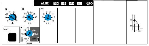
SM2 43ME: protection of motor for SM2-400\630 |
| |
|
1. Overload protection with adjustable threshold, as defined by IEC60947-4 (2) tripping class 10A,10 and 20 |
2. Short-circuit protection with adjustable threshold (6...13xIr) |
3. Phase failure protection (built-in electronic release: operates unbalanced single-phase currentat 40% and more than )(tripping time delay 4s¡À10%),as defined by IEC60947-4.1 |
4. Load indication : Flashing more than Ir setting threshold |
5. Fault indication |
LEDs indicates the type of fault that caused tripping
Overload (LT protection) or abnormal component temperature (>Ir);
Short-circuit (ST or instantaneous protection)( >Im);
Phase failure (right LED);
Microprocessor malfunction ( (>Ir) ( >Im) and phase failure LEDs all go on )
Battery powered. Spare battery are supplied in an adapter box. When a fault occurs ,the LEDindicating the type of fault ,lights for about 10 minutes . The information is however stored inmemory . The LED can be illuminated by pressing the test pushbutton. The LED automaticallygoes off and the memory is cleared when the circuit breaker is reset . |
| |
| Type |
Rated current In(A) |
Note |
SM2-400 |
400 |
Ir=0.4~1×In(adjustable 48 setting)
Trip degree: class 10A, 10,20(IEC60947-4)
(Long-time overload protection)
Im=6-7-8-9-10-11-12-13×Ir
(Short-circuit protection) |
SM2-630 |
630 |
|
| |
| |
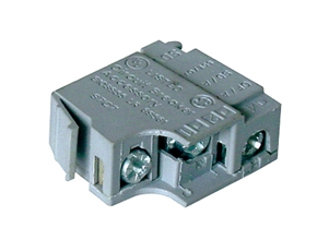
4.Accessories |
| |
| Accessories |
Rated operating voltage |
Consumption |
For type |
| Pick-up |
Seal-in |
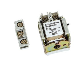
| Shunt release(MX) |
24V
100V
220/230V
380/400V |
<10VA |
<5VA |
SM2-100~630 |
| Under-voltagerelease(UN) |
220/230V
380/400V |
<10VA |
<5VA |
|
| |
| Accessories |
Rated operating voltage |
Consumption |
For type |
| AC12 |
AC15 |
Auxiliary contact(OF) |
380/400V |
6 |
3 |
SM2-100~630 |
Alarm contact(AL) |
380/400V |
6 |
3 |
|
| |
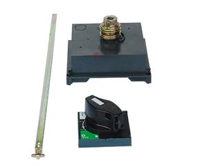
Rotary handle
Direct rotary handle
Degree of protection:IP40
Function:
1) suitability for isolation
2) indication of three positions 0(off) I(on) and tripped
3) press "push to trip" button, can trip-free
4) visibility of and access to trip unit settings
5) the circuit breaker can be locked in the off position by one to three padlocks , diameter 5 to 8mm(not supplied)
Extended rotary handle
Degree of protection:IP55
Function:
1) Suitability for isolation
2) Indication of three positions 0(off) I(on) and tripped
3) Visibility of and access to trip unit settings when the door is open
4) Door opening prevented when circuit breaker is on
5) The circuit breaker can be locked in the off position by one to three padlocks , diameter 5 to 8mm(not supplied).Locking prevents opening of the switchboard door
5.Installation
Circuit breaker may be mounted vertically, horizontally or flat on their back without any derating of characteristics.
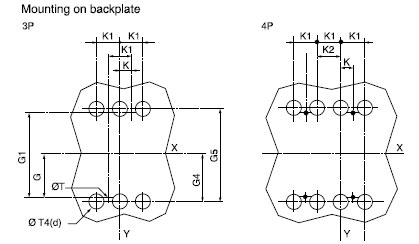
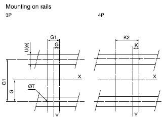
6.Fix
Mounting on backplate , mounting on rails
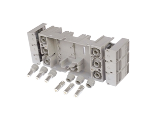
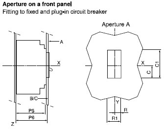
7.Connection
Front panel connection , black panel connection , plug-in connection
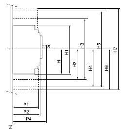
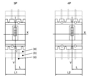
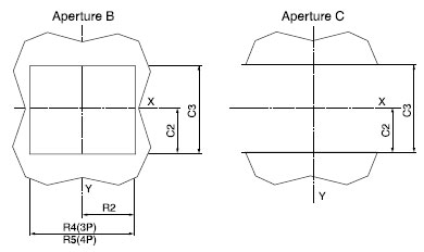
8. Outline and Installation Dimension |
| |
|
| |
| |
|
| |
| |
|
| |
| |
|
| |
| |
|
| |
| |
|
SM2-100~630 |
| |
mm |
C |
C1 |
C2 |
C3 |
G |
G1 |
G4 |
G5 |
H |
H1 |
H2 |
SM2 100/160/250N/H/L |
29 |
76 |
54 |
108 |
62.5 |
125 |
70 |
140 |
80.5 |
161 |
94 |
SM2 400/630N/H/L |
41.5 |
116 |
92.5 |
184 |
100 |
200 |
113.5 |
227 |
127.5 |
255 |
142.5 |
|
| |
| mm |
H3 |
H4 |
H5 |
H6 |
H7 |
K |
K1 |
K2 |
L |
L1 |
L2 |
P1 |
P2 |
P4 |
P5 |
SM2 100/160/250N/H/L |
188 |
160.5 |
321 |
178.5 |
357 |
17.5 |
35 |
70 |
52.5 |
105 |
140 |
81 |
86 |
111* |
83 |
SM2 400/630N/H/L |
285 |
240 |
480 |
237 |
474 |
22.5 |
45 |
90 |
70 |
140 |
185 |
95.5 |
110 |
168 |
107 |
|
| |
| mm |
P6 |
R |
R1 |
R2 |
R4 |
R5 |
φT |
φT4 |
(Ue) |
SM2 100/160/250N/H/L |
88 |
14.5 |
29 |
54 |
108 |
143 |
6 |
22 |
≤32 |
SM2 400/630N/H/L |
112 |
31.5 |
63 |
71.5 |
143 |
188 |
6 |
32 |
≤32 |
|
| |
*P4=126 is suitable for=SM2 250N/H/L |
|